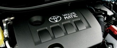
The various car manufacturers’ race to develop systems to reduce emissions, consumption and increase performance of their engines has led the Japanese Toyota brand to develop its Valvematic intake valve variable lift control system.
The Valvematic system, in coordination with the VVT-i dual system (variable valve timing), carries out the continuously variable intake valve lift control, as well as controlling the actuation angle of the intake valve, the full opening of the throttle valve and the synchronisation of the intake valve in accordance with engine conditions. This improves engine performance and saves fuel. The intake valve lift varies between 0.09 mm and 11 mm in accordance with engine needs.
One of the particular features of this system is that the intake manifold throttle is fully opened (like a diesel) in order to reduce pumping losses at all engine speeds. The Valvematic system will act based on the information that the ECM (engine control module) has collected from the TDC (engine rpm) and NTC (coolant temperature) sensors, the exhaust and intake camshaft position Hall sensors, from the MAF (Mass Air Flow) sensors and from the intake throttle position sensor and through the EDU (servomotor control unit), and it will open the intake valves between the aforementioned 0.09 mm and 11 mm according to needs so that the engine runs at the speed required by the driver.
This system requires the use of a vacuum pump to provide the correct vacuum to control the brakes, this is because the throttle is fully open and there can be no difference in pressure between its faces.
OPERATION
Depending on the data sent by the ECM (engine control module) to the EDU (servomotor control unit), the latter will command the Valvematic servomotor to make an axial extension or retraction movement to the control shaft, which will, in turn, transmit the movement through the helical pinions to the intake valve pushers.
OPERATING SCHEMATIC
Components
|
Function
|
ECM
|
The ECM determines the amount
and duration of the valve travel necessary for controlling the overall
operation of the engine, and sends commands to the EDU. Also, the ECM
receives information from the EDU for the engine control module to use.
|
EDU
|
The EDU calculates the required
rotation angle of the brushless motor rotor based on the commands sent from
the BCM, and actuates the brushless motor. Furthermore, the EDU detects the
rotation angle of the rotor and sends this information to the ECM.
|
Brushless motor
|
The rotor rotates using the
energy provided by the EDU.
|


Positive site, where did u come up with the information on this posting?I have read a few of the articles on your website now, and I really like your style. Thanks a million and please keep up the effective work. nebulizzatore condensa
ReplyDelete