Pages

Wednesday, 31 August 2016

New concepts: new engines

The research carried out in recent years by petrol engine manufacturers has focussed on the battle to lower CO2 emissions (considered a cause of global warming).
Compliance with the magic figure of 130 gr/km valid until 2020 has got the engine development departments working flat out. This figure is the only one that has led to a radical rethink of the modern engine, as the Euro 4 to Euro 6 standards do not significantly differ as regards the polluting gases measured for approval (CO, HC and NOx).

The Lambda 1 petrol engine is a high generator of CO2, in fact in the catalytic converter two oxidations and a reduction occur, CO2 being a large part of the results.


Today, the only way to reduce CO2 emissions lies in reducing consumption. At the moment there is no system or device that assists the engine in lowering this emission.

Thursday, 18 August 2016

Types of active suspension (l). Hydroactive 3 for Citroën C5

In an ideal suspension system, the position of the wheels would not change with respect to the body. The purpose of the various active suspension systems is to control the stiffness of the damping.

In hydraulic and air systems, the height of the vehicle is also controlled depending on variations in weight and road conditions. Electronic and electro-mechanical systems are required for this. In this and subsequent posts, three examples of this type of suspension are going to be described: the Citroen C5 Hydroactive 3, the Audi A8 Air suspension and the VW Golf DCC Adaptive Chassis Control.

In this first post, we are going to look at the Hydroactive 3 suspension.

Hydroactive 3 from Citroën C5

This type of suspension allows the distance to the ground to be varied automatically depending on speed. There are two positions, sport and comfort, which automatically change the stiffness of the damping. These changes give greater stability due to the lowering of the centre of gravity by 15 mm at the front and 11 mm at the back, which reduces fuel consumption. On poor roads, the system can raise the height of the vehicle by up to 13 mm.

Hydroactive 3 facilitates choosing between the two suspension options, it allows switching, alternately and in real time, from a soft setting, which gives priority to comfort, to a hard one to improve stability, while taking into consideration the driving style and the road profile at all times.

The main elements involved in the system are:

1. Integrated hydroelectronic block.
2. Front bearing elements.
3. Front stiffness regulator with its sphere.
4. Front height sensor.
5. Rear hydropneumatic cylinders
6. Rear stiffness regulator with its sphere.
7. Rear height sensor.
8. Control unit.
9. Steering angle sensor.
10. Hydraulic fluid tank.
11. Accelerator pedal position sensor.
12. Braking pressure sensor.
-A simplified hydraulic system.


Tuesday, 16 August 2016

The required and correct maintenance of the particulate filter (FAP)

In 2010, the Euro 5 standard came into force that requires car manufacturers to install a Particulate filter (DPF or FAP), among other elements, in the exhaust systems of diesel engines.
The purpose of the FAP is to store soot particulates generated by the incomplete combustion of the fuel, which drastically reduces the harmful particulate levels emitted to the atmosphere.

The FAP is a particularly effective mechanical filter which is made up of honeycomb type cells that trap the particulates emitted during combustion. It can retain more than 99% of the combustion particulates.


Particulate filter

To regenerate the Particulate Filter and prevent internal saturation with soot, the system carries out a regeneration process. This process is activated when certain technical temperature and running conditions are fulfilled. When these conditions are met, the engine control unit starts this process by acting on the injection system in order to raise the temperature inside the particulate filter, and thus burn the soot accumulated in it.

Tuesday, 2 August 2016

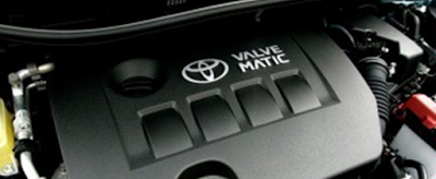
How does the Valvematic system work?

VALVEMATIC - INTAKE VALVE VARIABLE LIFT CONTROL TECHNOLOGY
The various car manufacturers’ race to develop systems to reduce emissions, consumption and increase performance of their engines has led the Japanese Toyota brand to develop its Valvematic intake valve variable lift control system.


The Valvematic system, in coordination with the VVT-i dual system (variable valve timing), carries out the continuously variable intake valve lift control, as well as controlling the actuation angle of the intake valve, the full opening of the throttle valve and the synchronisation of the intake valve in accordance with engine conditions. This improves engine performance and saves fuel. The intake valve lift varies between 0.09 mm and 11 mm in accordance with engine needs.

One of the particular features of this system is that the intake manifold throttle is fully opened (like a diesel) in order to reduce pumping losses at all engine speeds. The Valvematic system will act based on the information that the ECM (engine control module) has collected from the TDC (engine rpm) and NTC (coolant temperature) sensors, the exhaust and intake camshaft position Hall sensors, from the MAF (Mass Air Flow) sensors and from the intake throttle position sensor and through the EDU (servomotor control unit), and it will open the intake valves between the aforementioned 0.09 mm and 11 mm according to needs so that the engine runs at the speed required by the driver.

This system requires the use of a vacuum pump to provide the correct vacuum to control the brakes, this is because the throttle is fully open and there can be no difference in pressure between its faces.


Tuesday, 26 July 2016

Fault message: "Start of injection timing regulation" - Code 17656 in a VW Golf IV (1J5).


Our incident review department has confirmed the solution to a fault that affects the Volkswagen model - GOLF IV Variant (1J5) with 1.9 TDI engine that records a DTC of origin 17656 which tells us that there is a start of injection timing regulation fault in one of the cylinders as its regulation limit has been exceeded. This code is accompanied by various symptoms in the vehicle's engine performance. Below are detailed all the symptoms that appear:
·                     17656 - Start of injection timing regulation. Regulation incorrect. Cylinder 1, 2, 3 or 4. Regulation limits exceeded or below.
·                     Lack of engine power.
·                     Engine malfunctioning.
·                     Difficulty when starting the engine.
·                     Malfunction indicator lamp (MIL) on.


NOTE: This technical note only affects those vehicles equipped with an injection pump.

The following causes may be responsible for the aforementioned symptoms to occur:

·                     The service interval has been exceeded.
·                     There is dirt in the fuel tank and this dirt has clogged the fuel filter.

The solution that our workshop care and support department has successfully carried out is as follows:
·                     Read the fault codes in the engine control unit with the diagnostic tool.
·                     Confirm that the cited fault code is recorded that is mentioned in the symptom field of this technical note.
·                     Check that there is an optimal fuel level.
·                     Ask the customer if they have filled up with a suitable fuel.
·                     Check for leaks in the fuel supply circuit.
·                     Check for fuel impurities and quality.
·                     Replace the fuel filter.
·                     Clear the fault code recorded in the engine control unit.

It should be borne in mind that although the replacement of the fuel filter has prevented the majority of repetitions of this incident in our department, it is possible that the fault is due to another affected component, depending on the symptoms and type of vehicle. 


To be able to extract the fuel gauge correctly, the clips that secure it must be removed with great care. There are three securing clip positions for the fuel gauge which are located as shown in the image.


Tuesday, 19 July 2016

Park assist


Park assist systems are designed to help the driver during parking manoeuvres. The most used systems are those with ultrasonic parking sensors or a rear camera. 


Ultrasonic parking system

This is based on the use of sensors installed in the bumpers distributed strategically to cover a wide area. These sensors are mounted on the rear bumper and optionally on the front and are controlled by a control unit. 


The system is activated automatically on engaging reverse gear, the sensors are activated and emit an ultrasonic pulse that travels through the air. If there is an obstacle, the ultrasonic pulse will rebound from it and return to the sensor which will detect the pulse and inform the control unit. The control unit makes the calculation of the distance to the obstacle based on the time elapsed between the emission and the reception of the pulse. The maximum detection distance is approximately 0.8 to 1 metre.


The control unit emits an acoustic warning so that the driver knows the distance of the obstacle. These warnings are transmitted through independent loudspeakers or through the vehicle's audio system. As the vehicle nears an obstacle, the repeat rate of the audible warning increases. When the object is less than 30 centimetres from the centre of the vehicle’s bumper, the acoustic warning will sound continuously. 


Wednesday, 13 July 2016

Engine fault indicator light on


VW POLO 9N / IBIZA 6K

In this post, a fault is considered that causes the engine fault warning light to remain permanently on.


The models that can be affected are the following:

VW POLO 9N Motor 1.4-1.2 (BBY-AZQ) VW POLO 9N Engine 1.4-1.2 (BBY-AZQ)
SEAT IBIZA 6L Motor 1.4-1.2 (BBY-AZQ) SEAT IBIZA 6L Engine 1.4-1.2 (BBY-AZQ)


SYMPTOMS


- The engine fault light comes on.

- The vehicle jerks slightly.

- Excessive fuel consumption.


Tuesday, 5 July 2016

Fault in the fuel flow control solenoid valve – KIA Engine J3 2.9 CRDi


MAKES AND MODELS AFFECTED


KIA:
KIA CARNIVAL / GRAND CARNIVAL III (VQ) 2.9 CRDi (J3) 136 kW (185 CV) ’06-

The manufacturing date of the affected vehicles: 
03.2006 (start of production) to 10.12.2007.


SYMPTOMS

The symptoms that may be found are the following:
Engine fault indicator light (EOBD) on.
Fault message on the instrument panel multifunction screen.
The engine control unit enters an emergency/reduced power phase.

The following fault code is recorded on the diagnostics machine:

P0088 – Pressure too high in the fuel common rail. 

There may be more associated fault codes seen on the diagnostic machine.

Tuesday, 28 June 2016

Fault: Codes B1012 and B1020 on reading the CIM of an Opel Vectra C


The vehicle displays two specific fault codes in the control unit integrated into the steering column:

B1012 – Steering wheel angle sensor not calibrated.

B1020 – Steering wheel angle sensor. Functioning or limit value problem.

The fault indicator light for the stability control system (ESP) is on on the instrument panel when driving the vehicle.

The warning indicator light for the electro-hydraulic steering system (EHPS) is on on the instrument panel.


The indicator light stalk may malfunction, it does not return to its initial position.


 The cause of this fault is nothing more than a internal failure of the steering angle sensor (SAS), which is located inside the control unit (CIM) integrated in the electro-hydraulic power steering column (EHPS system). Unfortunately, due to the soldering of the sensor in the unit, it is not possible to repair it separately to reduce the cost of the fault repair, the complete module (CIM) must be replaced with an up-to-date version.

Monday, 20 June 2016

Checking power supplies

We are going to do a bit of revision, and what better than an everyday example:

A vehicle comes into our workshop that does not start or does so with difficulty.


We verify that it does not start, and then the first thing we do is check the existing or stored errors using the diagnostic apparatus.


 On the diagnostic machine we see that there is an injection relay error. Next, and due to the ease of testing another relay, we replace this relay to see if it is indeed malfunctioning (this is a common 20 amp relay, and there are bound to be some in the workshop), we fit the new relay and test it.
The car continues to have the fault and does not start, there is no other option but to start checking the installation.
Related Posts Plugin for WordPress, Blogger...